 The
spare wheel of the Cowley is supported in a well in the nearside mudguard and
held in place by a curved clamp which is in turn held down by a handwheel.
The
spare wheel of the Cowley is supported in a well in the nearside mudguard and
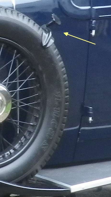
held in place by a curved clamp which is in turn held down by a handwheel.In this first picture an incorrect handwheel is shown.
The Spare Wheel Clamp on the 1932 Morris Cowley 2-seater Tourer
The
spare wheel of the Cowley is supported in a well in the nearside mudguard and
held in place by a curved clamp which is in turn held down by a handwheel.
In this first picture an incorrect handwheel is shown.
This was a temporary one of an inadequate diameter and had an insufficient
number of finger indents, Additionally it was not drilled and tapped all the way
through so as to permit a firm grip on the tyre.
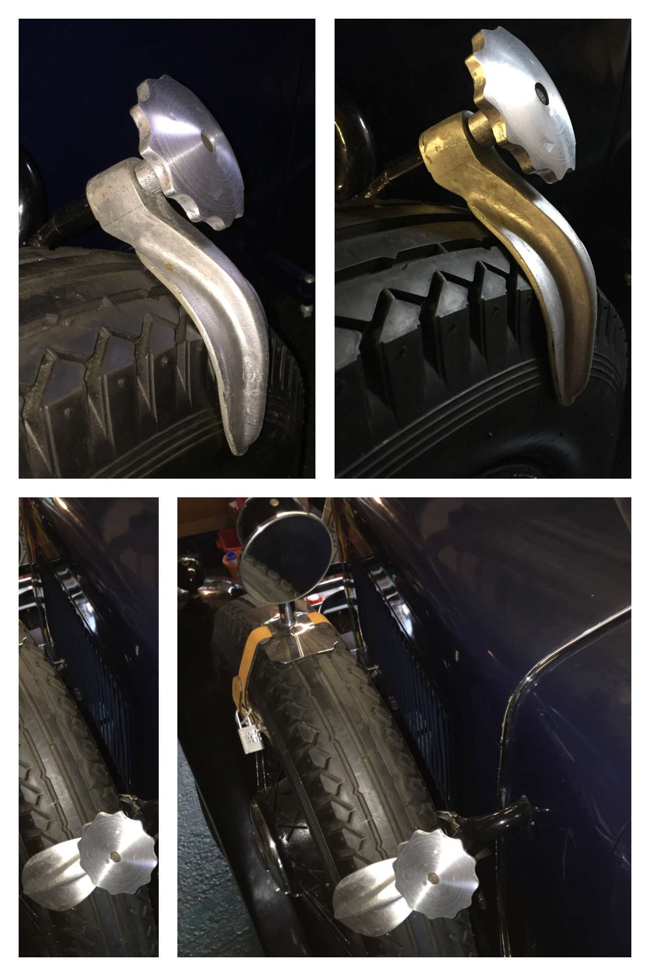
However, the clamp as shown here is the actual zinc alloy original though (not shown) is the
damage where the hole, which slides over the threaded support, had broken.
However the original was still able to be used as a pattern for a new aluminium
casting. All that was needed was a pattern for the handwheel.
A drawing was therefore prepared from memory of a better handwheel; one much more like the
original. This was used to make a wooden/clay pattern which could be held and
tried for suitability and feel. In the event the foundry felt that the
hand made wood and clay model could be used as the pattern.
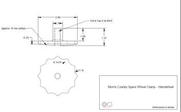
Click on the image for a PDF of this engineering drawing.
The casting of these two items was very skilfully performed by Archway Brown Ltd of Hitchin, though of course the rather 'naive' nature of my hand made handwheel pattern meant that rather more finishing was needed as well as the usual drilling and tapping of the final casting. I was able to drill the newly cast clamp with my own facilities but a colleague with a lathe very kindly drilled, tapped and shaped the handwheel for me.
A composite image of the finished result - though seen before final painting - is shown immediately below and a series of images taken during the machining process can be seen below these.
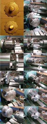
The Machining of the Handwheel.
My rather amateurish model in wood and modelling clay had originally only been made to confirm the size, suitability and shape of the needed handwheel. No previous images were available of the (now lost) original one, last seen by me some fifty years ago, and so it all had to be done from my memory of its use and feel. Going further to use it as the actual pattern for the casting saved a lot of money and so it was worth a try. The result proved to be adequate but the shaft and the domed top were not exactly concentric and the surface finish - especially of the domed part of the handwheel itself - was not very good.
After cleaning up the resulting wheel to get rid of some casting warts,
it
was decided to use a four jaw dependent chuck for extra grip. A centre drill was
used to establish the pilot hole. Then, because of the tendency for aluminium to
'grab', increasing drill sizes were used in 1 or 0.5 mm steps. A Whitworth
tapping drill of the correct size was the last to be used. Some images of
the process can be seen in a PDF which may be accessed by clicking on the
composite thumbnail image to the left. The separate images may then be
enlarged on screen.
The tailstock drill was used to position the tap, square on the hole, and then
with the lathe in neutral the tap was started by turning the lathe chuck
by hand with tailstock unlocked. After that the tap wrench could be used.
Tidying up the wheel 'dome' was performed simply by using some very coarse emery
paper at first, hand held and pressed hard against the dome at high speed. There
was a lot of metal to remove to get rid of the irregularities, and some could not
be completely removed.
As for the ‘finger indents’, these were draw-filed in a bench vice using a fine half round file, then the whole put it back in the lathe and held against some emery paper.
My thanks are due to Archway Brown Ltd for their casting skills and to Mr Graham Aldred both for his excellent work and for the photographs taken of the machining process.
[Back]