Putting the Doors back on!
The 1932 Morris Cowley Tourer metal body is formed around an ash frame which neither sits on nor is fixed to, the chassis proper.
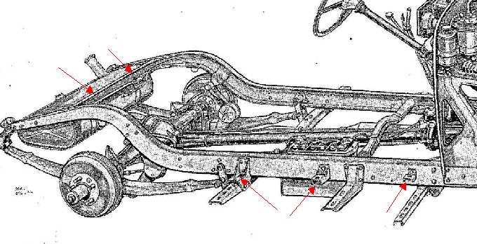
It sits on small outriggers on either side of the car and on the cross beam at the rear
- just in front of the petrol tank. The diagram below indicates with red arrows
those that are visible in the image. The other, longer outriggers support
the running boards.
 The
frame is first slackly bolted to these outriggers, rear fixings and to the car
bulkhead using coach bolts, washers and nuts. However if it were to be
simply bolted down tight to these, the doors will generally not fit nor properly shut.
To remedy this it is necessary to support the body on shims, the thickness of
which is each adjusted by trial and error to permit the doors properly to align
with their apertures in the body. The shims can be anything up to 3/8th
inch (9.5mm) but half that is more usual.
The
frame is first slackly bolted to these outriggers, rear fixings and to the car
bulkhead using coach bolts, washers and nuts. However if it were to be
simply bolted down tight to these, the doors will generally not fit nor properly shut.
To remedy this it is necessary to support the body on shims, the thickness of
which is each adjusted by trial and error to permit the doors properly to align
with their apertures in the body. The shims can be anything up to 3/8th
inch (9.5mm) but half that is more usual.
Selection of the correct thickness at each point can be a slow process in which the
choice might even seem counter intuitive.
However the effect of one side's adjustment on the other is not as much as one
might think. In the case of my car it also proved necessary to forcibly
open up the driver's side front pillar joint slightly with a jack and to pack the opened
joint to ensure it stayed open. However this was less a consequence of the
lie of the timber frame than it was of an aged joint between one upright and the
rest of the frame which had closed whilst the body was off the car.
The shims themselves have to be made to suit but they may be
made
from any suitable relatively non-crushable material. Hard plywood is fine.
Because of the sensitivity of this adjustment, it may even be necessary to fine
tune the thickness of each outrigger-shim using something like roofing felt.
Prior to undertaking this task a replacement set of hinge pins,
balls and springs should be used if the originals show any signs of wear.
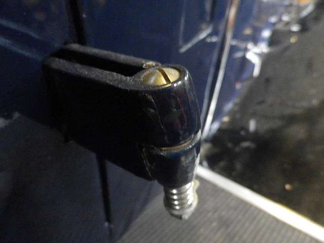
The Morris Cowley of this period uses what are known as self-aligning hinges.
See the image below left. These work on the basis of a brass ball between two cups all of which is held in place by a spring-loaded bolt
which passes through the ball and cups and is secured and prevented from
loosening by a nut and bent washer. Four such are used, two on each door.
Spare hinge pin and ball assemblies are available from
Vintage Car Parts.
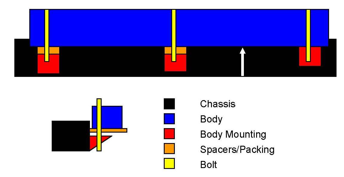
The image, above right, shows diagrammatically how alignment may be
achieved by careful shimming. (Image courtesy Radlett Classic
Cars LLP).
The white up-arrow indicates the mid-point of the door aperture
and the way that shims may be used to open up the aperture to allow a good fit
of the door. An excellent article that describes this form of adjustment
- but for early American Ford cars - can be found at:
http://www.abarnyard.com/workshop/door-2.htm
There are other aspects at this same URL which apply to saloons as well as
tourers.
Please note that the above article refers to American cars
and as such some of the terminology may be strange to British eyes/ears!
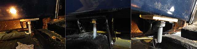
Here are some images that show the finally chosen shims actually in place on my
Morris Cowley. [Images taken for me on my camera by Radlett Classic Cars LLP]
The Matter of the Door Locks!
Once the doors have been located properly into their apertures,
the striker plate, the two rubber door stops and the locating peg and its
aperture can all be fitted into the door frame. At this point, the door might
well be persuaded to shut. However in my case the door had to be slammed
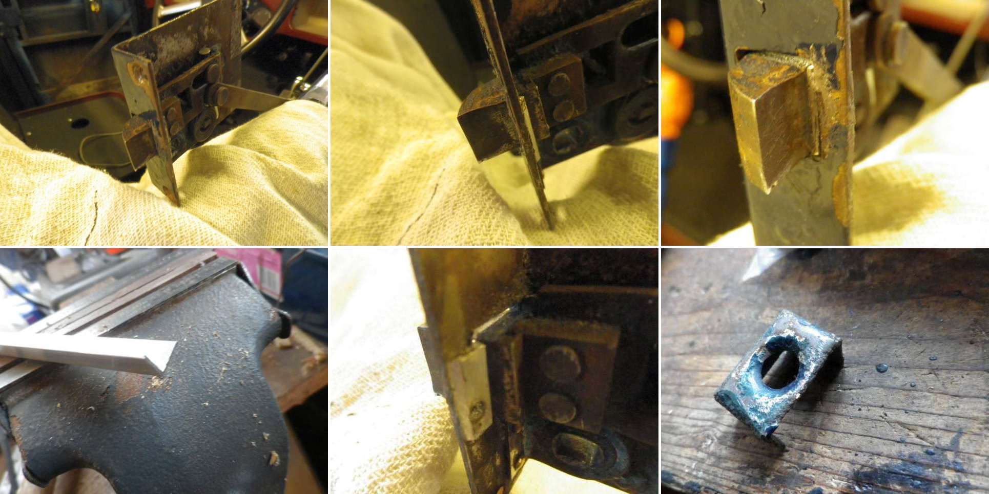
very hard for it to close and lock. Inspection showed that in each case the cause was that the
lock itself was worn. The locks on this model of Cowley do not have
fully enclosed casings and so they may readily be detached and the interior inspected even
whilst the internal door release mechanism is still attached - see the images
below. There are four
wood screws securing it to the wooden frame of the door: two short ones in the
end face and two longer ones in the body. Care should be taken to protect
the paintwork of the top edge of the door when the sharp-edged case is being
examined whilst the internal release mechanism is still attached.
There were two areas of wear. First and foremost, the
rectangular aperture in the end of the lock case, through which the bolt operates, was about
a millimetre, or more, wider than the bolt. This play ensured that when the door
was being shut the bolt moved back away from its intended place and so never
fell behind the
striker plate - unless of course the door was slammed shut. Secondly the internal bolt's end-stop was worn so allowing the bolt
to extend some 2-3mm out too far such that the bolt was then not easily pushed in
by its radiussed end as the door was closed. The images below show the
lock interior, the way that a small piece of 1mm thick 'L' shaped aluminium was
cut and filed to suit. It was also drilled to provide a further key for
the epoxy glue and then was glued into place to
locate the lock-bolt's position more toward the interior of the car. The pictures also show the
way that the bolt was further prevented from extending too far out through its
end plate by the simple expedient of a masonry nail inserted at the back of the
lock.
After degreasing the area with 'meths' and with the lock parts
clamped against the backplate, the prepared aluminium filler bracket was secured by using 'J-B
Weld', a metallicised form of epoxy resin. It too was temporarily clamped in place whilst the
resin set. Also shown in the last image below is one of the four metal holders
used to retain the rubber door stops that prevent vibration etc once the door has
shut. The necessary 'T' shaped rubbers for fitting into these are available from Vintage Car Parts.
However they may need to be trimmed with a knife a little to suit. Spray grease was then used to lubricate the lock before final reassembly.
A pleasant 'clunk' now follows attempts to shut the door.
The newly chromed exterior handle and bar was then provided with
a hand cut rubber washer (to prevent damage to the door paint and to limit
ingress of water) before being secured to the door using countersunk
stainless screws.

***NB: In addition to Radlett Classic Cars LLP
for the diagram and for taking some of the above photographs,
I am also indebted for the above web link and for other advice on this matter to
members of the British Morris Register whose names, sadly, following a loss of emails, I
am now unable to acknowledge here. If they read this and would
care to email me again with their names I shall be delighted to acknowledge
them.
[Back]